Deck 1: Surveying a yard with a laser level
Deck design step 1: Accurate surveying with a laser level, and creating a 3D model of the yard.
I want to have a clear idea of how my stairs will land, and whether I’ll keep enough height below the lower tier of my deck to meet local building codes. I laid out a 3′ grid in the general area of the future deck, and then, using a laser line level and a yard stick, I took height measurements at each point on my grid.

First I cut some simple wooden stakes and drove them into the yard at 3′ intervals, straight back from each side of the house.

Using this old umbrella stand as a post, I mounted a laser level in one corner, at a position where the beam angle covered the entire yard.
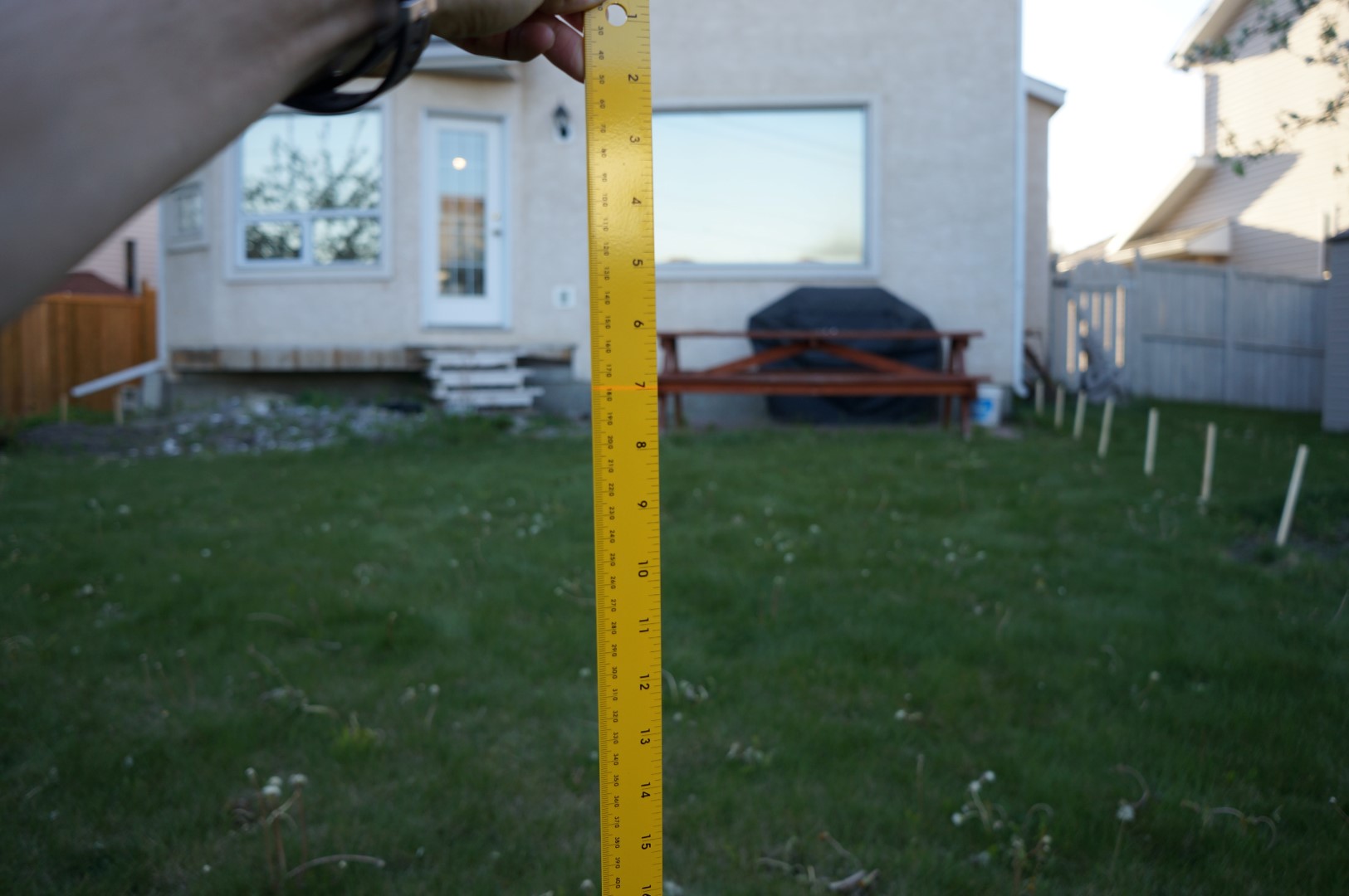
With a measuring tape stung between each pair of stakes, I took a height measurement every 3′. I found that I had to do this at dusk to be able to see the line when I was at the far corner from the laser level. A white yard stick would have done a better job reflecting the laser line than this yellow one. My grid was 30′ by 30′, so in total I collected 100 measurements.
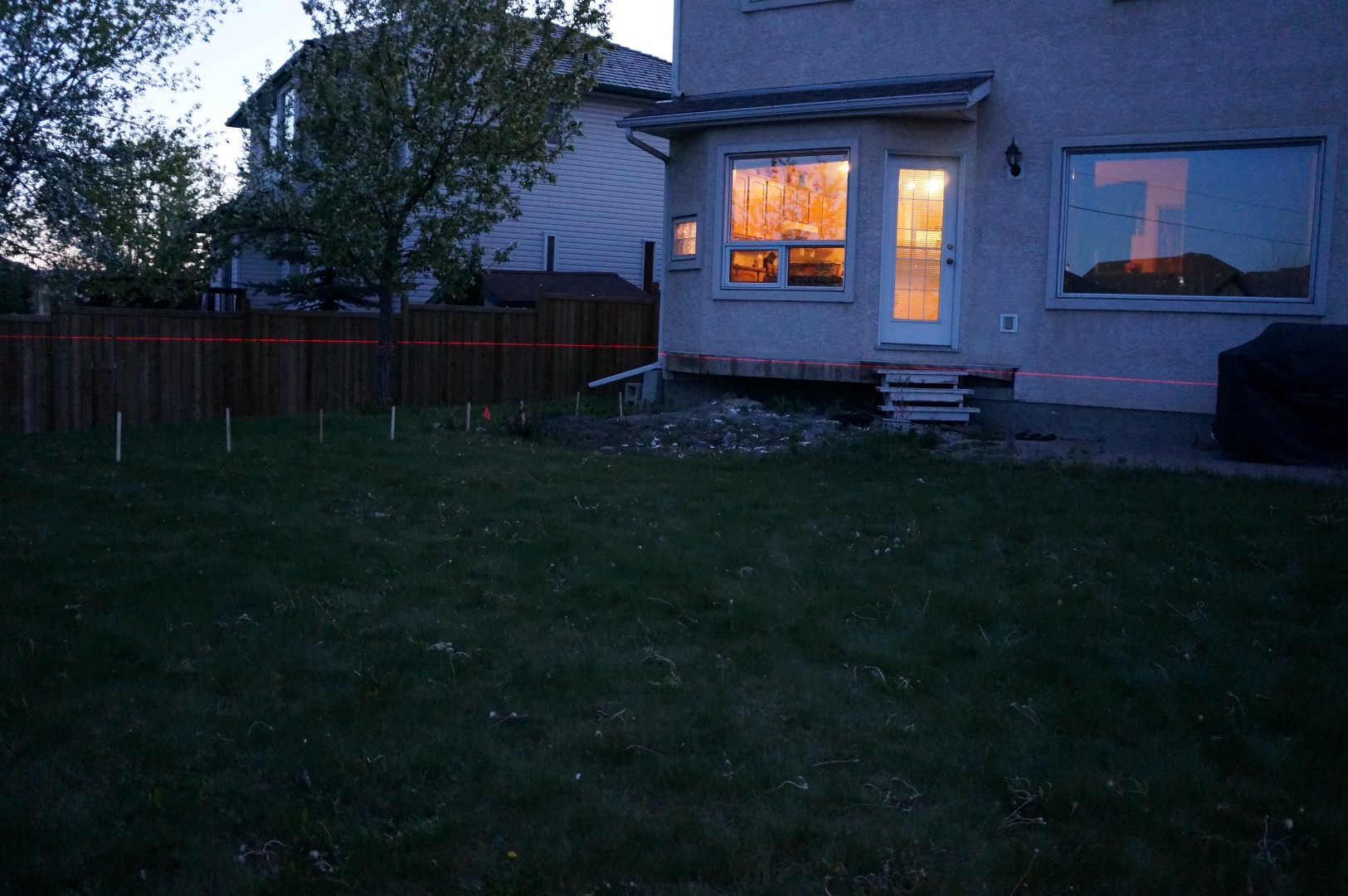
The laser became easily visible after the sun set. Before moving the laser I also took measurements from the line to several references on the house such as the door threshold and the line between the parge and the stucco. Having these datum measurements is critical for properly aligning the house model to the survey model.
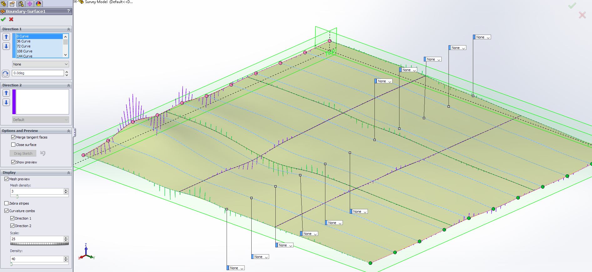
I split the data up into rows, and then used Solidworks’ “Insert Curve through XYZ Points” function to input each row as a curve. Lastly, I pulled all the curves into a Boundary Surface.
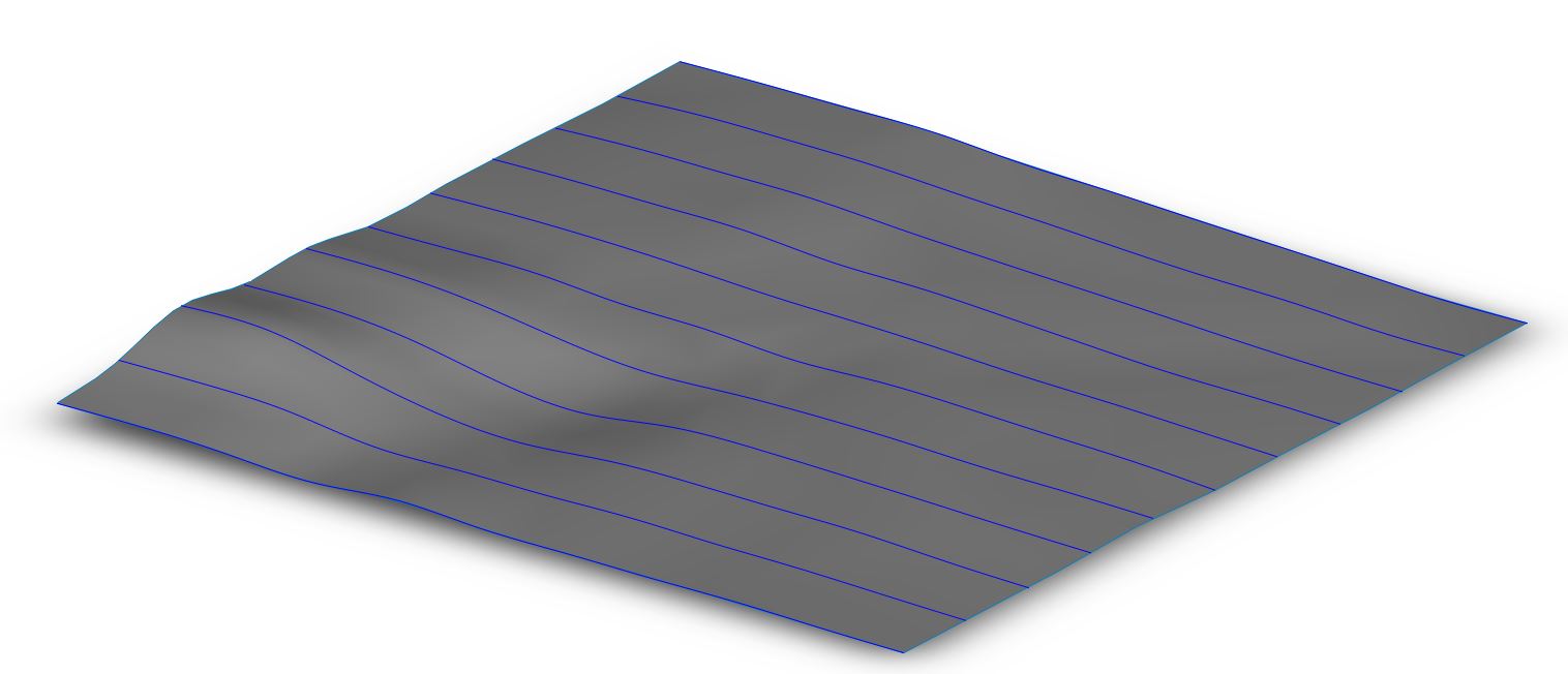
Very pleased with the end result. Next step is to start designing the deck!